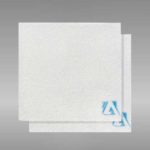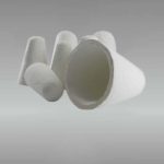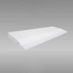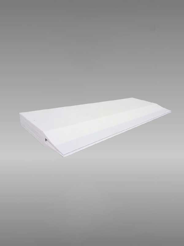
A caster tip is a precision-engineered nozzle component used in aluminum continuous casting and rolling lines to distribute molten aluminum uniformly across the roll gap, directly controlling crystal formation, strip thickness, and surface quality of aluminum sheet and foil blanks. Made from nano-scale fiber composite materials through vacuum suction filtration molding, a properly designed caster tip eliminates white stripes, dark lines, and surface defects—problems that cost producers thousands of dollars in scrap per shift. Below, we break down materials, structure, performance specs, and selection criteria based on real production data.
If your project requires the use of Caster Tip, you can contact us for a free quote.
Dimensions (mm)
| Item | Length | Width | Thickness of tip | R radius | Shape |
| Value | 200-2300 | 50-600 | 1.6-10 | Constant value | Enterocoelia/Level |
Parameters
| Item | Density (g`cm3) |
Rupture modulus (816℃·Mpa) |
Thermal Expansivity (680℃·K-1) |
Thermal Conductivity (540℃w/m`k) |
Max Working Temperature(℃) |
|
| Typical value | Roll-PH | 0.45-0.57 | 42-48.8 | 1.35-1.56*10-6 | 0.12-0.15 | 1260 |
Instructions:
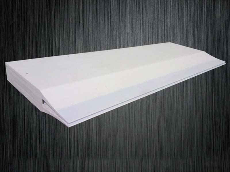
Caster Tip
Request A Quote
Why Does Caster Tip Quality Determine Your Cast-Rolling Output?
If you’ve ever run a twin-roll casting line, you already know: the caster tip is where everything either comes together or falls apart. It’s the last component molten aluminum touches before solidification, and any inconsistency here—uneven flow, thermal gradient, fiber shedding—shows up immediately on the finished coil.
In practice, the caster tip controls three things simultaneously:
- Molten aluminum distribution — Uniform flow across the full strip width (typically 800–2100 mm) prevents edge cracking and centerline segregation.
- Thermal stability — The tip must maintain consistent temperature in the casting zone, usually within ±3°C, to ensure uniform grain structure.
- Surface contact integrity — Any delamination or particle drop contaminates the strip surface, a problem you can’t fix downstream.
This is why switching from a mediocre supplier to a precision-manufactured tip often yields measurable improvements in first-pass yield—sometimes 4–6% gains within a single campaign, based on field reports from Middle Eastern and Southeast Asian smelters running 8xxx and 1xxx series alloys.
For an overview of how caster tips integrate with upstream ceramic foam filters and online degassing equipment , those systems work in tandem to deliver clean, thermally stable metal to the nozzle.
What Is a Caster Tip Made Of?
Modern caster tips are manufactured from nano-scale fiber composite material, formed through vacuum suction filtration. This process produces a body with uniformly distributed short fibers—critical for consistent thermal conductivity and mechanical strength at operating temperatures (680–720°C for most aluminum alloys).
The key material properties that matter in real production:
- Moderate bulk density (typically 0.6–0.9 g/cm³) — light enough for good insulation, dense enough to resist erosion
- High oxidation resistance — essential during extended campaigns lasting 20+ hours
- No delamination or block drop — the internal fiber structure must hold together under thermal cycling
- Compatibility with boron nitride (BN) coating — most operators apply a BN coating to the working surfaces, and the substrate must bond well for the coating to perform
Material Composition Comparison
| Property | Standard Fiber Tip | Nano-Fiber Composite Tip | Graphite-Based Tip |
|---|---|---|---|
| Fiber Distribution | Moderate uniformity | Highly uniform | N/A (solid) |
| Max Service Temp (°C) | 750 | 800 | 850 |
| Bulk Density (g/cm³) | 0.7–1.0 | 0.6–0.9 | 1.6–1.8 |
| BN Coating Adhesion | Fair | Excellent | Poor |
| Risk of Particle Shedding | Moderate | Very Low | Low |
| Typical Campaign Life (hrs) | 15–25 | 25–40 | 30–50 |
Nano-fiber composite tips offer the best balance between thermal insulation, coating compatibility, and resistance to slag drop—three factors directly tied to strip surface quality.
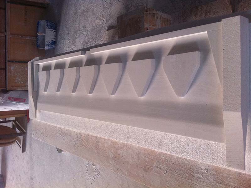
Tip Cavity
Caster Tip Structure and Components
A complete caster tip assembly consists of several precision-matched components, each serving a specific function in the casting process:
- Nozzle Plate — The primary working surface that contacts molten aluminum; machined to tight tolerances to ensure uniform gap width across the roll face
- Gasket — Provides a thermal and mechanical seal between the nozzle plate and the supporting structure, preventing metal leakage
- Ears — Side-sealing elements that contain the molten aluminum pool at the strip edges; critical for preventing edge bleed and controlling strip width
- Flow Control Box — Regulates metal feed rate and distribution before the aluminum enters the nozzle cavity
- Fixture — Mounting hardware that positions the tip precisely relative to the casting rolls; must allow fine adjustment during operation
- Runner — Internal channel system designed with symmetrical flow paths to satisfy aluminum liquid hydrodynamic requirements and deliver even flow
Each of these parts must be manufactured and assembled to dimensional tolerances typically within ±0.1 mm. Even small misalignments between the nozzle plate and the roll surface create uneven solidification fronts—and that’s where you start seeing the dark lines and white stripes that downgrade your coil.
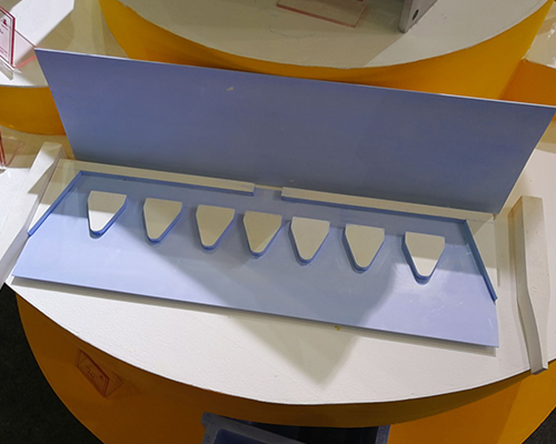
Molten Aluminum Caster Tip Structure and Components
How Does AdTech Caster Tip Design Affect Aluminum Foil Surface Quality?
1. Symmetrical Flow Channel Geometry
The internal runner system must distribute aluminum symmetrically across the full width of the nozzle. Asymmetric flow creates localized hot spots and cold zones, which produce:
- White stripes — caused by uneven solidification speed
- Dark lines — typically from localized turbulence or oxide entrainment
- Thickness variation — which compounds through subsequent cold rolling passes
Well-designed tips use CFD-optimized (computational fluid dynamics) channel geometries. The goal is laminar flow at the nozzle exit with velocity variation under 5% across the strip width.
2. Dimensional Precision and Low Deformation
High-precision equipment processing keeps the size tolerance small—critical because the nozzle-to-roll gap typically ranges from 5–8 mm and must stay consistent. Any tip deformation under thermal load shifts this gap unevenly, making it nearly impossible to produce flat, gauge-consistent strip.
Low deformation also means easier gap adjustment during production. Operators who’ve switched from conventional tips to precision-made alternatives consistently report faster setup times and fewer mid-campaign adjustments.
3. Nano-Coating Reinforcement on Critical Surfaces
Key contact areas receive nano-coating reinforcement that serves two purposes: it prevents slag from dropping into the melt (which would create inclusions in the strip), and it resists chemical attack from molten aluminum. Aluminum is surprisingly aggressive toward most ceramic materials above 700°C—without proper coating, fiber erosion accelerates rapidly after 15–20 hours of operation.
Combined with a boron nitride surface coating, these reinforced tips routinely achieve 30+ hour campaigns without measurable degradation. For mills running continuous casting and rolling lines with high uptime targets, that durability translates directly to reduced changeover costs.
If your project requires the use of Caster Tip, you can contact us for a free quote.
Caster Tip Performance Specifications
Key Dimensional and Thermal Parameters
| Parameter | Typical Range | Why It Matters |
|---|---|---|
| Nozzle Width | 800–2150 mm | Must match roll face width |
| Lip Thickness | 3–6 mm | Affects heat transfer rate at solidification front |
| Operating Temperature | 680–720°C | Alloy-dependent; tip material must be stable across range |
| Dimensional Tolerance | ±0.10 mm | Governs strip thickness uniformity |
| Thermal Conductivity | 0.15–0.25 W/m·K | Low values preferred for insulation |
| Max Continuous Use | 25–40 hrs | Depends on alloy aggressiveness and BN coating quality |
Dimensional tolerance is the single most overlooked specification—many surface defect issues traced back to the caster tip originate from out-of-spec lip geometry rather than material failure.
How to Extend Caster Tip Service Life
Based on operational data from casting lines across China, the Middle East, and India, several practices consistently extend tip life:
Pre-heat protocol matters. Ramping the tip from ambient to operating temperature too quickly causes micro-cracking in the fiber matrix. A gradual preheat over 2–3 hours—matching the thermal expansion rate of the composite material—prevents early failure.
BN coating application technique. Uneven coating thickness is a common problem. Two thin coats with intermediate drying outperform one thick coat every time. Target 0.2–0.3 mm total dry film thickness on all surfaces contacting molten metal.
Alignment verification. Before every campaign, verify tip-to-roll alignment using feeler gauges at minimum five points across the nozzle width. A 0.05 mm misalignment at the lip creates a detectable stripe on the finished coil.
Alloy transition management. When switching from a less aggressive alloy (e.g., 1060) to a more aggressive one (e.g., 5052), inspect the tip thoroughly. Mg-containing alloys attack the fiber matrix faster, and a tip that looks fine after a 1xxx campaign may fail within hours on a 5xxx alloy.
For production lines using degassing units upstream, cleaner incoming metal also reduces chemical attack on the tip, indirectly extending service life.
Caster Tip Installation: Common Mistakes That Cause Defects
Even a perfectly manufactured caster tip will underperform if installation is botched. These are the errors we see most often:
- Insufficient gasket compression — Leads to micro-leaks that oxidize and create edge defects
- Ear misalignment — Causes uncontrolled strip edge geometry and potential metal breakout
- Over-torquing fixtures — Cracks the nozzle plate, especially on tips with thinner wall sections
- Skipping the flow test — Running water through the assembled tip before casting reveals blockages and asymmetry that you won’t detect visually
- Ignoring thermal soak time — Pushing metal through a cold tip creates thermal shock cracking; always complete the full preheat cycle
These details aren’t glamorous, but they account for the majority of caster tip-related quality complaints in practice. Getting the basics right eliminates most problems before they start.
FAQ
1. What is a Caster Tip?
A Caster Tip is a key component in aluminum casting and rolling lines. It controls molten aluminum flow, crystal formation, and strip size.
2. What does a Caster Tip do?
A Caster Tip distributes molten aluminum evenly into the roll gap. This helps improve thickness control and surface quality.
3. What material is a Caster Tip made of?
Most high-performance Caster Tips are made from nano-scale fiber composite materials. These materials provide insulation, oxidation resistance, and low deformation.
4. Why is Caster Tip accuracy important?
High dimensional accuracy helps keep the nozzle gap stable. This reduces white stripes, dark lines, and thickness variation.
5. Can a Caster Tip improve aluminum foil quality?
Yes. A well-made Caster Tip helps produce smoother foil stock with fewer surface defects and better coil consistency.
6. Which aluminum products use a Caster Tip?
Caster Tips are widely used for aluminum foil stock, PS plate base, flexible packaging materials, and other cast-rolled aluminum products.
7. How long does a Caster Tip last?
Service life depends on alloy type, coating, and operating conditions. In stable production, a quality Caster Tip can support long casting campaigns with low deformation.
8. Does a Caster Tip need boron nitride coating?
In many applications, yes. Boron nitride coating improves release performance and helps protect the Caster Tip from molten aluminum attack.
9. When should a Caster Tip be replaced?
A Caster Tip should be replaced when it shows deformation, erosion, cracking, coating failure, or when strip surface defects begin to increase.
10. How do I choose the right Caster Tip?
Choose a Caster Tip based on alloy series, strip width, required tolerance, and target surface quality. Material stability and precise machining are both critical.